


You probably think mesh WiFi setup means scrolling through confusing menus, rebooting routers six times, and crossing your fingers. That’s what happens when you skip the basics. ASUS AiMesh setup is actually straightforward if you match firmware versions first, choose the right backhaul method for your home, and add nodes in the correct order. This guide walks you through prerequisites, primary router configuration, backhaul planning, and satellite pairing so your mesh works on the first try.
Prerequisites and Requirements Before Starting Setup

Proper prep prevents most AiMesh headaches. Before you power anything on or start clicking around, spend 15 minutes checking your hardware compatibility, matching firmware versions, and gathering the right cables. Most failed setups? They trace back to skipped prerequisites, not technical complexity.
Compatible Router Models
You need at least two compatible ASUS routers. One becomes your primary router, the others turn into satellite nodes. Here’s what works with AiMesh:
RT-AX86U / RT-AX86U Pro – High performance dual band with 2.5Gbps port
RT-AX86S – Budget version of the AX86U, skips the 2.5Gbps port
RT-AX55 / AX58U / AX3000P – Affordable dual band options for smaller homes
TUF-AX5400 – Gaming focused dual band, solid wireless performance
ZenWiFi XT8 / XT9 / XT12 – Tri band mesh systems, come pre synced in packs
RP-AX58 / RP-AX56 – Range extenders that double as AiMesh nodes
GT-AXE16000 / GT-BE98 Pro – Premium multi gig routers for Wi-Fi 6E and Wi-Fi 7
ZenWiFi Pro ET12 – Tri band system built for wired multi gig backhaul
ZenWiFi and ExpertWiFi packs ship pre synced from the factory. They’re already paired and ready to work together. Mixing routers from different product lines or generations? Expect to spend more time on setup. Mixed Wi-Fi standards (Wi-Fi 5 + Wi-Fi 6, Wi-Fi 6 + Wi-Fi 6E, Wi-Fi 6E + Wi-Fi 7) work better with wired backhaul. Avoid mixing dual band and tri band routers in wireless setups unless you’re ready for reduced performance.
Firmware Version Requirements
All routers in your mesh must run matching major firmware versions before you try forming the mesh. ASUS uses version numbers like 386, 388, and ASUSWRT 5.0. If your primary runs firmware 388 and your satellite runs 386, the mesh won’t form reliably. You’ll see connection drops.
Update each router individually as a standalone unit before attempting mesh setup. Connect to each router separately, log into the web interface, check for firmware updates, install them. Don’t skip this even if a router’s brand new. Factory firmware is often outdated.
Avoid initial major releases. When ASUS drops a new major firmware version like 388.0 or 5.0.0, wait for the first minor update (388.1 or 5.0.1) before upgrading. Early releases often have bugs that mess with mesh stability. Want the most stable experience? Wait six months after a major release.
Required Hardware and Cables
Gather these before starting:
Ethernet cables – Cat5e, Cat6, or Cat6a all work for wired backhaul. You need one cable connecting your primary router’s WAN port to your modem or ONT. Using wired backhaul between nodes? You’ll need additional cables running from the primary router’s LAN ports to each satellite’s WAN port.
Multi-Gig switch – Only needed if you’re using 2.5Gbps or faster backhaul connections. Standard gigabit switches bottleneck faster connections.
Modem or ONT connection – Your primary router connects directly to your internet source via its WAN port. Satellites never connect to the modem.
Computer or smartphone – You need at least one device to access the router’s configuration interface. For manual setup methods, you may need two devices or one computer plus a smartphone running the ASUS Router app.
Complete Primary Router Setup and Configuration

Your primary router is the foundation for your mesh network. All settings, firmware updates, and network management happen through this router’s interface. Use the web GUI at 192.168.50.1 or router.asus.com for initial setup instead of the mobile app. The app can cause inconsistencies during mesh formation that lead to failed node additions.
Here’s the complete setup process:
- Connect the primary router’s WAN port (usually blue) directly to your modem or ONT using an ethernet cable
- Power on the router and wait until the LED is solid, not blinking (takes 1 to 2 minutes)
- Connect your computer to the router via ethernet cable or Wi-Fi using the default network name printed on the router label
- Open a web browser and go to 192.168.50.1 or router.asus.com (older models may use 192.168.1.1)
- Log in using default credentials, typically admin/admin unless changed by the previous owner
- Run the quick setup wizard when prompted and follow the on screen steps
- Set the network SSID to “Auto” during initial setup (this is critical for node compatibility)
- Create a strong admin password when prompted and write it down somewhere secure
- If the router prompts for a firmware update, install it now and wait for the automatic restart
- Verify internet connection by opening a new browser tab and loading a website
- Note the router’s IP address for future access (usually 192.168.50.1)
The “Auto” SSID setting during initial mesh formation isn’t optional if you want reliable node detection. This setting ensures satellites can discover and connect to the primary router without manual SSID matching. After all nodes are added to the mesh, you can customize network names through the web interface under Wireless settings.
DHCP and LAN IP configuration happens automatically for most users. The router assigns itself 192.168.50.1 as the gateway address (or 192.168.1.1 on older models) and manages IP address distribution to connected devices. You don’t need to change these settings unless you have specific networking requirements or conflicts with existing equipment.
Backhaul Connection Methods and Topology Planning
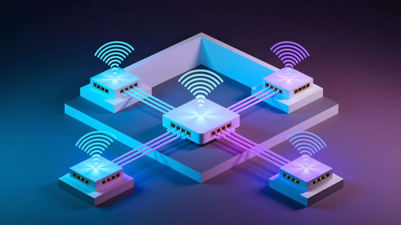
The backhaul connection links your satellite nodes to the primary router. This connection carries all internet traffic for devices connected to satellites, making it the most important performance factor in your mesh network. Wired backhaul using ethernet cables connected to each satellite’s WAN port is strongly recommended for reliability and performance. Wireless backhaul works but reduces total available bandwidth because one radio band must handle both backhaul traffic and client devices.
Topology patterns affect performance and reliability. Star configuration means all satellites connect directly to the primary router. This is ideal for wireless backhaul because each node maintains a strong connection to the primary. Daisy chain configuration means satellites connect through other satellites. This works acceptably for wired setups where cable runs prevent direct connections to the primary router, but it increases latency and reduces speeds for devices on downstream nodes.
| Connection Method | Setup Process | Performance Impact | Best Use Case |
|---|---|---|---|
| Wired Backhaul | Run ethernet cable from primary router LAN port to satellite WAN port | Full bandwidth available to clients, no wireless interference, lowest latency | Multi story homes with existing ethernet runs, high bandwidth users, 4K streaming, gaming |
| Wireless Backhaul | Place satellite within range of primary router, system auto detects and connects | One band dedicated to backhaul reduces client bandwidth by 30 to 50%, subject to interference | Rentals without cable access, temporary setups, homes under 2,000 sq ft with open floor plan |
Tri band routers dedicate one 5GHz band exclusively for wireless backhaul, leaving two bands (2.4GHz and the other 5GHz) available for client devices. This reduces the bandwidth penalty but doesn’t eliminate it. The dedicated backhaul band is no longer available to clients. Dual band routers share one of their two bands between backhaul and clients, cutting available bandwidth roughly in half.
Cable compatibility is straightforward. Cat5e, Cat6, and Cat6a all work for wired backhaul up to gigabit speeds. For 2.5Gbps or 10Gbps connections, you need Cat6a or better and a Multi-Gig switch between the primary router and satellites. Standard gigabit switches bottleneck faster connections.
Ethernet Backhaul Mode is a setting that optimizes performance in pure wired setups by disabling unnecessary wireless coordination between nodes. This improves speeds and reduces latency, but you must disable it before adding new nodes. The system won’t detect new satellites while this mode is active.
Advanced backhaul settings let you optimize specific hardware configurations. If you have a Multi-Gig router with 2.5Gbps or 10Gbps ports, manually select which port handles backhaul traffic in the satellite node settings. For Wi-Fi 7 systems, use MLO (Multi-Link Operation) for the fastest backhaul speeds. Wi-Fi 6E systems should use the 6GHz band for wireless backhaul in open spaces with line of sight, or 5GHz when distance or obstacles are present.
Adding Satellite Nodes to Your Mesh Network
Satellites should be placed 10 feet from the primary router during initial pairing, or connected via ethernet cable from a primary LAN port to the satellite WAN port. This close proximity or wired connection ensures the strongest possible signal during the pairing process when the system establishes encryption keys and backhaul parameters.
The automatic addition process:
- Ensure the satellite has matching firmware version (same major version like 388 or ASUSWRT 5.0) and is factory reset
- Place the satellite 10 feet from the primary router, or connect an ethernet cable from any primary router LAN port (yellow or black) to the satellite’s WAN port (blue)
- Power on the satellite and wait until the LED is solid, not blinking (takes 1 to 2 minutes)
- On your computer, access the primary router web GUI at 192.168.50.1 or router.asus.com
- Navigate to Network Map in the left sidebar
- Click the AiMesh Node section
- Click the Search button
- Wait 1 to 2 minutes without clicking away, refreshing the page, or opening other tabs
- Verify the node appears in the topology map with a connection quality indicator showing Great, Good, OK, or Weak
- After the first satellite is added, manually restart the primary router from the Administration section
- Wait 3 to 4 minutes for the system to fully restart before adding additional nodes
The connection quality indicator (Great/Good/OK/Weak) reflects signal strength and backhaul speed between the primary router and satellite. Aim for Good or better. If you see OK or Weak, reposition the satellite closer to the primary or switch to wired backhaul.
Manual Node Addition Method (When Automatic Search Fails)
Automatic search fails in about 20 to 30% of initial setups, usually due to firmware mismatches, weak wireless signals, or timing issues. The wired manual method works when automatic detection doesn’t.
Connect an ethernet cable from any LAN port on the primary router to the WAN port on the satellite. Log into the satellite’s admin panel directly by connecting a second computer or smartphone to the satellite’s default Wi-Fi network and navigating to 192.168.50.1 (or the satellite’s default IP if different). Go to the Administration tab, select the “AiMesh Node” radio button, and click Next. The satellite will spend several minutes converting itself from router mode to node mode. The interface will become unresponsive during this process, and the LED will blink. After conversion completes and the LED becomes solid, access the primary router’s web GUI and use the Search function in Network Map > AiMesh. The converted node should appear within 30 seconds.
This manual method requires two devices: two computers, or one computer plus a smartphone with the ASUS Router app installed. You need simultaneous access to both the primary router and the satellite during the conversion process.
If a node needs to be factory reset, hold the WPS button for 5 to 10 seconds until the LED starts flashing rapidly. Release the button and wait for the router to complete the reset process, which takes 1 to 2 minutes. The router will reboot and return to factory settings with the default network name and password printed on the label.
Optimal Node Placement and Coverage Planning
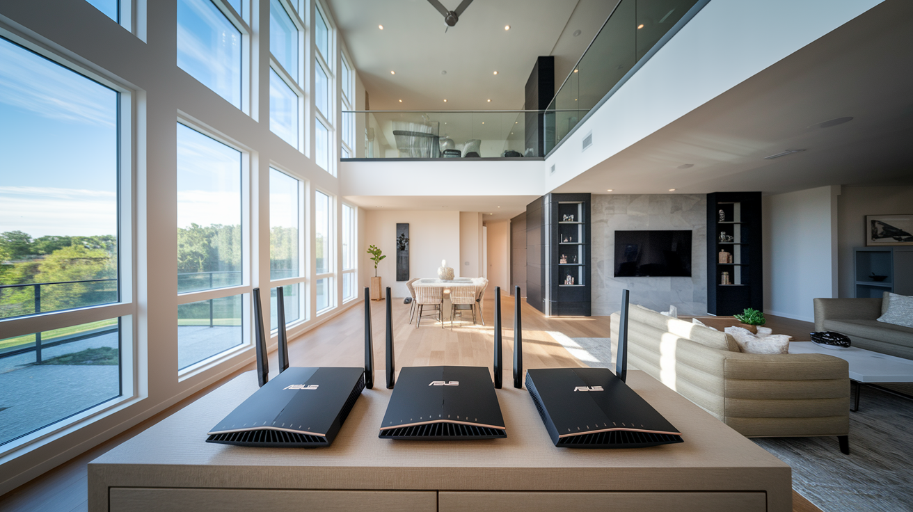
After initial pairing at 10 feet distance or via temporary ethernet connection, reposition nodes for optimal whole home coverage. The goal is balancing strong connection quality to the primary router with elimination of dead zones in your intended coverage areas. Check the connection quality indicator (Great/Good/OK/Weak) in the Network Map after moving each node to a new location.
Node placement guidelines:
Position nodes centrally within their intended coverage zones. Middle of the room works better than corner placement.
Maintain Good or better connection quality to the primary router (or parent node in daisy chain wired setups).
Avoid placement near concrete walls, brick, or metal studs that block Wi-Fi signals. These materials reduce signal penetration by 50 to 70%.
Elevate nodes off the floor for better signal propagation. Place on a shelf, desk, or mount on wall.
Ensure adequate ventilation clearance around units. Avoid enclosed cabinets or tight spaces that trap heat.
Plan multi story coverage strategically (primary at front of main floor, satellite at back of main floor, satellite in basement maximizes coverage).
Consider future expansion zones like upstairs hallways if bedroom reception becomes an issue after initial deployment.
Leave nodes accessible for occasional reboots and ethernet cable connections.
Test coverage by walking through your home with a smartphone, checking signal strength bars, and loading a webpage or streaming a video in each room. The system should hand off your device seamlessly between nodes without manual network switching. You’ll stay connected to the same SSID as you move from room to room.
Star topology (all satellites maintaining strong direct connections to the primary router) is recommended for wireless backhaul setups. This maximizes performance and reliability. Daisy chain topology is acceptable for wired configurations where cable runs make direct connections impractical, but each additional hop adds 5 to 10ms latency and reduces maximum throughput by 10 to 15%. Placement flexibility increases significantly with ethernet backhaul because connection quality no longer depends on wireless signal strength. You can position nodes purely based on coverage needs rather than wireless range limitations.
Network Settings: SSID, Security, and Band Configuration
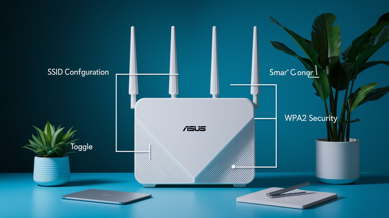
After the mesh is formed, customize SSID names in the Wireless settings section of the primary router’s web GUI. The initial “Auto” setting used during setup can be replaced with your preferred network name. You have two main options: a single SSID via Smart Connect that covers all bands (2.4GHz, 5GHz, and 6GHz if available), or separate names per band like “HomeNetwork2.4″ and “HomeNetwork5″ for manual control.
Smart Connect lets devices automatically choose the best band based on signal strength, capabilities, and congestion. This works well for most users and creates a seamless experience where devices switch bands without you noticing. Separate SSIDs per band give you manual control. Useful if you have devices that perform better on specific bands or if you want to force high bandwidth devices onto 5GHz.
WPA2 is recommended over WPA3 for network security, especially if you have older devices or IoT products. The security difference between WPA2 and WPA3 is minimal for home networks, but WPA3 causes compatibility issues with devices manufactured before 2019. Stick with WPA2 unless you have a specific security requirement.
| Setting | Recommendation | Configuration Notes |
|---|---|---|
| SSID Strategy | Smart Connect (single SSID) | Automatic band selection, seamless device switching, less manual management |
| Security Protocol | WPA2 | Maximum compatibility with older devices and IoT products, minimal security difference from WPA3 |
| Channel Selection | Auto | System selects least congested channels, manual selection only if persistent interference present |
| 6GHz Band (Wi-Fi 6E/7) | Enable in Professional settings | Requires explicit enablement and SSID configuration, use PSC for channel selection |
| Guest Network Structure | Guest Network 1 for system wide access | Guest Network 1 broadcasts from all nodes, other guest networks are node specific |
Guest network configuration starts in the Guest Network section of the web GUI. Guest Network 1 is special. It broadcasts from all nodes in the mesh, creating a unified guest network throughout your home. Guest Networks 2 and 3 are node specific, broadcasting only from the primary router or individual satellites where you enable them. The Intranet access toggle controls whether devices on the guest network can access local resources like printers, NAS devices, and other computers on your main network. Disable this toggle for true guest isolation.
Wi-Fi 6E routers with 6GHz capability require explicit enablement in the Professional settings under the Wireless section. After enabling 6GHz, configure an SSID for the band. It won’t broadcast without an assigned network name. Use PSC (Preferred Scanning Channels) with Auto channel selection for 6GHz operation. PSC channels reduce scanning time and improve device compatibility compared to non PSC channels.
Roaming Assistance and Device Handoff Configuration

The roaming threshold controls when devices switch between nodes based on signal strength, measured in dBm (decibel milliwatts). The default setting is -70 dBm, which means devices consider switching to a different node when their current connection drops to -70 dBm or weaker. Lower numbers like -60 mean stronger signals, while higher numbers like -75 mean weaker signals.
Access roaming settings through Wireless > Professional tab, with separate settings available for each band (2.4GHz, 5GHz, and 6GHz if available). You adjust the threshold per band based on how your devices behave in your home’s layout.
Roaming considerations:
-60 dBm setting causes more frequent roaming with consistently faster speeds. Devices switch to stronger nodes earlier, before connection quality degrades.
-75 dBm setting reduces unnecessary switching for stationary devices like smart TVs or desktop computers that don’t move between rooms.
Roaming Block List locks specific devices to designated nodes. Useful for devices that roam too aggressively or perform better connected to specific nodes.
Devices may not roam if their current connection meets bandwidth needs despite lower signal strength. Streaming video at -75 dBm may work fine, so the device stays put.
Toggling device Wi-Fi off/on forces immediate reconnection to the strongest available node. Quick fix when a device gets “stuck” on a distant node.
Smart Connect band handoffs can cause brief connection issues where devices appear connected but can’t access network resources. Disable Smart Connect if you see devices showing connected status but acting firewalled.
Proper setup enables seamless roaming between floors and rooms without manual network switching. You’ll move from basement to main floor to upstairs while streaming music or on a video call, and the handoff happens without interruption.
Balance roaming sensitivity based on your home’s layout and device types. Open floor plans benefit from more aggressive roaming settings like -60 dBm because devices move smoothly between coverage zones. Homes with many walls and closed doors work better with less aggressive settings like -70 or -75 to avoid unnecessary switching when signal temporarily weakens due to a closed door. Mobile phones benefit from aggressive roaming since they move between rooms, while stationary smart TVs don’t need frequent node switching.
Using the ASUS Router App vs Web GUI Interface
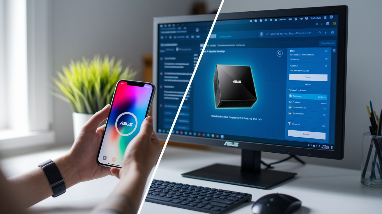
The web GUI at 192.168.50.1 or router.asus.com must be used for initial setup and mesh configuration. The mobile ASUS Router app can cause inconsistencies during mesh formation. Nodes may appear to add successfully but disappear after reboot, or firmware updates initiated through the app may fail partway through, leaving routers in inconsistent states.
After setup is complete and your mesh is stable, the app becomes useful for monitoring network status, viewing connected devices, and managing basic settings remotely. It’s convenient for quick checks and simple adjustments when you’re away from home or don’t want to open a laptop.
Interface comparison:
Web GUI advantages – Complete settings access including advanced wireless configuration, full troubleshooting tools like ping tests and logs, stable during node addition and firmware updates, detailed firmware management and version verification.
Mobile app advantages – Convenient real time monitoring of network and device status, quick device management and identification, easy parental control adjustments, secure remote access from outside your home network when properly configured.
Access the web interface by entering 192.168.50.1 in any browser while connected to the network (older models may use 192.168.1.1). The manual node addition method described earlier requires two devices, either two computers, or one computer plus a smartphone running the ASUS Router app for simultaneous access to both the primary router and the satellite being configured.
Troubleshooting Common AiMesh Setup Problems
Automatic node detection fails in roughly 20 to 30% of initial setups, and troubleshooting becomes necessary. A basic 2 node setup typically takes 15 to 30 minutes plus firmware update time, but failed detection can add an hour if you don’t know the workarounds.
| Problem | Cause | Solution |
|---|---|---|
| Node not found in search after 5+ minutes | Firmware version mismatch between routers, or satellite placed too far from primary | Verify same major firmware version on both routers, move satellite within 10 feet of primary, or connect temporary ethernet cable |
| Zero MAC address error during addition | Firmware incompatibility or incorrect setup sequence | Factory reset satellite, update firmware as standalone router first, then retry as node |
| Node disconnects immediately after wireless addition | Weak wireless signal or interference between primary and satellite | Try wired setup first with ethernet cable, then switch to wireless after successful pairing |
| Nodes disappear from topology map when wired | Ethernet Backhaul Mode enabled before all nodes added | Disable Ethernet Backhaul Mode in AiMesh settings, wait 2 minutes, search for missing nodes |
| Firmware update causes connection drops or instability | Major version release instability or corruption during update | Wait for minor version update release, or manually revert to previous firmware version |
| LED won’t stop flashing after setup attempt | Failed setup state, node stuck in pairing mode | Hard reset node by holding WPS button 5 to 10 seconds, start setup process from beginning |
| Setup takes longer than 30 minutes without completion | System performing background optimization and configuration | Allow 5 to 10 minutes for full startup after each change, avoid clicking away during node search |
| System unresponsive after settings changes | Automatic restart in progress after configuration change | Wait 3 to 5 minutes for automatic restart to complete, refresh browser, reconnect if necessary |
The hard reset process solves most stuck states and failed setups. Hold the WPS button on the satellite for 5 to 10 seconds until the LED starts flashing rapidly. Release the button and wait 1 to 2 minutes while the router completes the reset and reboots. The router returns to factory settings with default network name and password. Use this when automatic setup fails, firmware updates cause problems, or you want to start fresh.
The manual wired setup alternative works when wireless detection repeatedly fails. Connect an ethernet cable from any LAN port on the primary router to the WAN port on the satellite. Access the satellite’s admin panel by connecting a second computer or smartphone to the satellite’s default network and going to 192.168.50.1. Navigate to the Administration tab, select “AiMesh Node” mode, and click Next. Wait several minutes for the conversion process. The interface becomes unresponsive during this time. After conversion completes and the satellite LED becomes solid, access the primary router web GUI and use the Search function in Network Map > AiMesh. The converted node appears within 30 seconds.
Remove nodes through Network Map > AiMesh section by clicking the trash icon next to the node name. This also factory resets the node, returning it to standalone router mode with default settings.
Allow 5 to 10 minutes for full system startup after firmware updates, major settings changes, or manual restarts. The mesh needs time to re establish connections between nodes, optimize backhaul paths, and synchronize settings. Firmware version rollback is available if an update causes issues. Download the previous firmware from ASUS support, access the Administration > Firmware Upgrade section, and manually upload the older firmware file. After major firmware updates that cause problems, perform a factory reset on all routers, restore settings from backup (or reconfigure manually), and rebuild the mesh from scratch.
Performance Optimization and Quality of Service Settings

Expected wireless speeds on Wi-Fi 6E systems reach 500 to 700 Mbps even when you have 3Gbps internet service. This isn’t a limitation of the mesh system. It’s the reality of wireless transmission with real world interference, distance, and obstacles. Wired clients connected directly to router ethernet ports achieve full internet speeds. For most home uses including 4K streaming, video calls, and web browsing, 100 to 200 Mbps is sufficient.
Gaming benefits more from low latency than raw download speed. A stable 100 Mbps connection with 20ms latency performs better for online gaming than an unstable 500 Mbps connection with 60ms latency.
Optimization tips:
Use wired backhaul for best performance. Removes wireless interference and bandwidth sharing between backhaul and clients.
Enable QoS (Quality of Service) to prioritize gaming or streaming traffic over background downloads and updates.
Position nodes to avoid interference from other routers, microwaves, cordless phones on 2.4GHz band.
Use tri band routers to preserve client bandwidth by dedicating one band exclusively to backhaul traffic.
Disable unnecessary services like FTP servers, media servers, or VPN services if you don’t use them. Reduces CPU load.
Prioritize critical devices via QoS settings to guarantee bandwidth during congestion.
Wireless backhaul reduces available client bandwidth by dedicating one radio band to inter node communication. In dual band systems, this means the 5GHz band splits its time between backhaul traffic and client devices, cutting effective bandwidth roughly in half. Tri band routers mitigate this by dedicating an entire 5GHz band to backhaul while leaving the 2.4GHz band and second 5GHz band available exclusively for client devices. This doesn’t eliminate the bandwidth penalty. You still lose the dedicated backhaul band’s capacity for clients. But it prevents the severe performance degradation seen in dual band wireless mesh systems.
Managing Connected Devices and Network Monitoring
The Network Map tab shows your mesh topology, node connection quality (Great/Good/OK/Weak), and all devices currently connected to the network. Each node appears as an icon with lines showing how it connects to the primary router. Devices appear as smaller icons grouped under the node they’re connected to.
The AiMesh section under Network Map provides individual node management. Click any satellite node to access its specific settings: LAN port configuration, LED brightness controls, USB port settings, and manual backhaul priority selection. This is where you’d force a node to use a specific ethernet port for backhaul or disable LEDs if they’re too bright at night.
Monitoring capabilities:
View all connected devices by name, IP address, and MAC address in a sortable list.
See which node each device connects to. Helps identify if devices are connecting to distant nodes instead of nearby ones.
Check connection quality indicators showing Great, Good, OK, or Weak for each satellite’s backhaul connection.
Monitor real time traffic and bandwidth usage per device (requires AiProtection or Traffic Analyzer enablement).
Identify nodes in the topology map to verify mesh structure matches your intended layout.
Manage individual node settings including port configuration, wireless settings, and physical controls.
Device naming makes identification easier when you have 20+ devices connected. Click any device in the client list, then click the pencil icon to assign a friendly name like “Living Room TV” or “Kitchen Echo Dot” instead of the generic manufacturer name. Block or allow specific devices through the same interface. Useful for guest devices that should only have temporary access or IoT devices you want to restrict to specific hours.
Use the topology visualization to optimize node placement based on which devices connect to which nodes. If you notice bedroom devices connecting to the living room node instead of the upstairs hallway node, it indicates the upstairs node may need repositioning or the living room node’s signal is too strong and preventing proper roaming.
Advanced Configuration: Access Point Mode and Special Scenarios
Two main deployment scenarios exist for AiMesh: standard router mode and access point (AP) mode. Standard router mode means the AiMesh primary router connects its WAN port to your modem or ONT, handles all routing and DHCP, and satellites connect behind it. AP mode means an existing ISP gateway or router remains the primary router, and all AiMesh units operate as access points at the same network level. They provide Wi-Fi coverage without routing functions.
AP mode is necessary when you can’t bridge or disable routing functions on your ISP provided gateway. Many fiber ISPs and cable companies provide combination modem/router/Wi-Fi gateways that can’t be set to bridge mode, creating a double NAT situation if you connect another router behind them.
Special configuration considerations:
AP mode setup process – Connect primary AiMesh unit’s WAN port to ISP gateway LAN port, access web GUI, go to Administration > Operation Mode, select Access Point mode, allow system to reboot.
Bridge/passthrough mode for ISP gateways – Preferred over AP mode when available, allows AiMesh primary to handle all routing while ISP gateway only handles internet connection.
PPPoE passthrough workaround – Works for AT&T and similar ISPs that don’t offer true bridge mode, primary router handles PPPoE authentication while gateway passes traffic through.
Unmanaged switch requirement – Only unmanaged switches work reliably between primary router and satellites, managed switches cause connection drops unless VLANs are configured correctly to pass all traffic.
Port forwarding – Configure on primary router when using standard router mode, configure on ISP gateway when using AP mode.
VPN configuration – AiMesh primary can run VPN server or VPN client in standard router mode, but not in AP mode where routing is disabled.
Double NAT occurs when two routers on your network both perform Network Address Translation. Your ISP gateway assigns a private IP to your AiMesh primary router (like 192.168.1.x), then your AiMesh primary assigns another private IP range to your devices (like 192.168.50.x). This breaks port forwarding, causes problems with gaming consoles and peer to peer applications, and adds latency. AP mode or ISP gateway bridge mode solves double NAT by ensuring only one device handles routing. Performance and remote access improve significantly when double NAT is eliminated.
IoT Device Compatibility and Guest Network Isolation
Some older IoT devices have compatibility issues with Wi-Fi 6E and Wi-Fi 7 routers even when connected to dedicated 2.4GHz networks. The issue isn’t the Wi-Fi standard itself but how newer routers implement 802.11 protocol features. If you have IoT devices that refuse to connect or connect then immediately disconnect, you may need a separate older router dedicated to IoT devices.
| Device Category | Compatible Examples | Known Incompatible Examples |
|---|---|---|
| Security Cameras | Foscam, Nest, Wyze V4+ | Pre V4 Wyze cameras |
| Doorbells & Chimes | Ring Doorbell, YoLink sensors | Ring Chimes (older models) |
| Garage & Door Controllers | GLiNet routers with bridge mode | MyQ garage openers (2019 and earlier) |
| Thermostats | Honeywell thermostats | First gen Nest thermostats |
| Sprinkler Systems | Modern Rachio Gen 3+ | Orbit B-hyve, older Rachio models |
| Pool Controllers |