


You probably think mesh WiFi is just plug and play. But here’s the thing. Most people place their satellites way too far apart or wire them wrong, then wonder why their gigabit internet crawls at 100Mbps. The diagrams and floor plans below show you exactly where to position each node, how to wire ethernet backhaul when it matters, and when wireless placement actually works. You’ll see labeled examples of star topology, fully wired setups, and hybrid configurations that mix both methods so you can match what actually fits your home.
Complete Mesh Network Diagrams: Labeled Visual Examples From Modem to Satellites

The three diagrams below show complete mesh WiFi installations from your ISP equipment through to satellite placement. They cover wireless star topology, fully wired ethernet backhaul, and hybrid configurations that combine both methods.
Diagram 1: Wireless Star Topology shows your ISP modem connecting to the primary router’s WAN port. The router distributes signals wirelessly to 2-3 satellite nodes arranged in a star pattern. Each satellite sits 25-40 feet from the main router with no wireless hops between satellites. Signal strength indicators show full bars at the router dropping to 3-4 bars at each satellite location. All satellites connect directly back to the primary router, not to each other.
Diagram 2: Fully Wired Ethernet Backhaul displays the modem feeding the primary router, which connects via Cat6 cable to an unmanaged gigabit switch. The switch distributes ethernet connections to multiple satellite nodes throughout your home. Each cable segment gets labeled with specifications (Cat6 for gigabit speeds, Cat6a for multi-gig connections). This setup eliminates all wireless backhaul, dedicating the mesh system’s WiFi bands entirely to client devices rather than inter-node communication.
Diagram 3: Hybrid Wired/Wireless Setup combines both approaches strategically. The modem connects to the primary router as usual. An ethernet cable runs from the router to a distant satellite node positioned at the far end of your home or in a separate building. That wired satellite then wirelessly extends coverage to additional nodes within its range. The diagram clearly distinguishes wired segments (solid lines with ethernet labels) from wireless connections (dotted lines with distance measurements), showing how you can wire through problem areas then extend wirelessly where running cables isn’t practical.
| Component | Position in Network | Connection Method | Purpose |
|---|---|---|---|
| ISP modem/ONT | First device, connects to internet line | Coaxial or fiber from street | Converts ISP signal to ethernet |
| Primary mesh router | Second device, connects to modem WAN port | Ethernet cable to modem | Creates network and routes traffic |
| Satellite node, star configuration | Connects directly to primary router | Wireless backhaul in star pattern | Extends coverage with single wireless hop |
| Satellite node, wired backhaul | Connects via switch or direct ethernet | Cat6/Cat6a ethernet cable | Maximum performance extension point |
| Topology Type | Connection Method | Best For | Performance Level |
|---|---|---|---|
| Star wireless | All satellites connect directly to router wirelessly | Rentals, apartments, homes where ethernet isn’t practical | Good, single wireless hop maintains 70-90% speeds |
| Fully wired | Ethernet cables from router through switches to all satellites | New construction, renovations, homes with existing ethernet | Excellent, full gigabit or multi-gig speeds throughout |
| Hybrid wired/wireless | Ethernet to distant satellites, wireless extension from there | Existing homes with partial ethernet, multi-building properties | Very good, wired segments at full speed, wireless extends strategically |
Backhaul Configuration Guide: Wired, Wireless, and Hybrid Connection Options
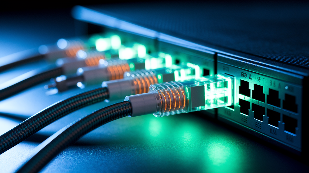
Backhaul is the connection method between your mesh nodes, separate from how your phones and laptops connect. This inter-node communication path determines your mesh network’s performance ceiling regardless of how fast your internet plan is.
Fully wired ethernet backhaul represents the gold standard for mesh performance. Your internet line feeds the modem, which connects to your primary router’s WAN port. From there, ethernet cables run to an unmanaged switch that distributes connections to satellite nodes throughout your home. You can arrange these physically in either daisy-chain or star patterns since the ethernet cable itself prevents performance degradation. For gigabit-plus internet speeds, you’ll need Multi-Gig Cat6a cables rather than basic Cat6. Regular Cat6 handles gigabit fine. But if you’re paying for 1.2Gbps or faster service, Cat6a ensures you actually get those speeds. Powerline adapters that use your electrical wiring don’t cut it for this purpose since they can’t maintain gigabit speeds reliably.
The bottleneck principle matters here. If you connect your multi-gig router to a basic gigabit switch, everything behind that switch maxes out at gigabit speeds no matter what your satellites can handle. Match your component speeds. A 2.5 gigabit router feeding a 2.5 gigabit switch to 2.5 gigabit satellites maintains full performance. Mixing in one gigabit switch drops everything downstream to gigabit. The slowest link determines the speed for all traffic passing through it.
Wireless backhaul works when ethernet isn’t practical, but stick with star topology. Each satellite connects directly back to your main router rather than hopping through other satellites on the way. This keeps you to a single wireless hop, which maintains decent speeds. If your mesh system detects satellites placed too far apart, it automatically drops backhaul traffic to the 2.4GHz band even when you’ve selected dedicated 5GHz or 6GHz backhaul in settings. You’ll notice this when speeds suddenly drop since 2.4GHz maxes out around 100-150Mbps in real conditions. Avoid daisy-chain wireless setups where satellites connect through other satellites since each additional wireless hop compounds signal loss and adds latency.
Hybrid configurations work well in practice. Run ethernet from your router to a strategically placed distant satellite, then let that wired unit extend wirelessly to additional nodes. This approach puts the wired connection where it matters most, covering the longest distance or penetrating through difficult materials, while wireless handles the easier extensions. Tri-band and quad-band systems excel at mixed setups since they dedicate specific bands purely for backhaul traffic in these configurations. A quad-band Wi-Fi 6E system might use 6GHz exclusively for inter-node communication while keeping 2.4GHz and 5GHz bands clear for your actual devices.
Common hybrid topology scenarios:
Ranch or hallway layouts work with wire to the satellite at the far end of the longest hallway or wing, then add a wireless satellite midway to eliminate the dead zone. Multi-building properties benefit from ethernet from main house to detached garage through conduit, wireless satellite inside garage for full coverage. Homes with one accessible ethernet run can wire to the second floor through existing cable chase, place wireless satellites on main floor extending from that wired upstairs unit. Apartments with single ethernet drop can run that to a satellite if you have one in-wall ethernet jack in a bedroom, wirelessly extend to the rest of your apartment. Split-level homes can wire to the lowest level through basement or crawlspace access, wireless satellites handle upper levels with better line-of-sight conditions.
Horizontal Placement Rules: Distance Guidelines and Floor Plan Positioning

Wireless backhaul placement depends on what’s between your nodes. In open areas or through standard drywall, place satellites 40-50 feet from your primary router. When signals must penetrate dense walls like brick, concrete, or multiple layers of standard framing, reduce that maximum distance to 25-30 feet. Wide open spaces with virtually zero obstacles can extend well beyond these ranges, sometimes reaching 100+ feet. But most homes have enough structure to bring you back to the standard guidelines.
Find the right satellite position by walking away from your router watching the 5GHz signal bars on your smartphone. Place your satellite where the signal drops one or two bars lower than what you see standing next to the router, but before you lose signal completely. This “one or two bars lower” sweet spot puts the satellite where it still receives strong backhaul signal while extending coverage into previously weak areas. If you place the satellite where your phone shows only one remaining bar or drops to 2.4GHz, you’ve gone too far and the mesh system will struggle to maintain fast backhaul speeds.
Square footage determines how many nodes you need based on typical residential construction. Two nodes (router plus one satellite) covers 1500-2000 square feet adequately. Three nodes handles 2000-3200 square feet by adding a second satellite. Homes between 3200-6400 square feet need four or more nodes to eliminate dead zones. Individual mesh nodes cover roughly 2000 square feet in typical homes with standard drywall and wood framing, though this drops significantly with dense materials or multiple interior walls.
Small ranch homes (1500-2000 sq ft) work with the router positioned centrally and one satellite at the far end. A 1600 square foot ranch might place the router in the living room with a satellite 35 feet away in the master bedroom covering the entire bedroom wing. Medium homes (2000-3200 sq ft) benefit from two satellites positioned to cover opposite wings or ends. Position your router centrally, perhaps in a hallway near the home’s midpoint, then place satellites 30-40 feet in opposite directions. Large homes (3200+ sq ft) require three satellites arranged around the perimeter with the router at the center. A 3800 square foot two-story might place the router on the main floor centrally, with satellites at opposite ends of the main floor and one upstairs centrally located.
| Home Size (sq ft) | Number of Nodes | Primary Router Location | Satellite Locations | Coverage Notes |
|---|---|---|---|---|
| 1500-2000 | 2 (router + 1 satellite) | Central living area | One satellite at far end, 35-45 feet from router | Adequate for single-story ranch or small two-story |
| 2000-3000 | 3 (router + 2 satellites) | Center of home near hallway intersection | One satellite each direction, 30-40 feet from router | Covers most two-story homes or sprawling single-story |
| 3000-4000 | 4 (router + 3 satellites) | Main living area, ground floor center | Two satellites on main floor at ends, one upstairs center | Eliminates dead zones in larger two-story construction |
| 4000+ | 5+ (router + 4+ satellites) | Most central location available | Strategic placement every 30-40 feet creating overlapping coverage | May require hybrid wired/wireless for consistent performance |
Vertical Deployment: Multi-Story Setup and Floor-to-Floor Coverage Strategy

Floor penetration reduces your effective wireless range by 30-50% compared to horizontal distances through walls. This makes dedicated nodes on each level essential for homes with two or more stories if you want consistent coverage. Concrete floors eat even more signal than wood framing with subfloor, and metal ductwork running between floors creates additional barriers that wireless signals struggle to penetrate.
Vertical alignment helps when your floor plan allows it. Placing satellites in rooms directly above or below each other creates the optimal signal path between floors since the wireless signal travels the shortest distance through floor materials. If your upper floor layout differs from your main floor, you’ll need to offset satellite placement strategically while maintaining 25-35 foot vertical separation measured floor-to-floor. A satellite in the main floor living room might align with an upstairs hallway location rather than a bedroom if that’s where you need the coverage and the vertical distance stays within range.
Mount satellites on upper floors at elevated positions. Wall-mounting near the ceiling or placing units on top of tall furniture enhances downward signal distribution to lower levels. Your main floor router should sit at medium height for balanced propagation both upward and downward. A router on a desk or shelf 3-4 feet off the ground distributes signal better than one tucked on the floor behind furniture. Upper floor satellites benefit from high mounting since signals propagate downward through floors more effectively than trying to push upward through the same materials.
Basements present special challenges. Concrete or stone foundations combined with earth contact severely limit signal penetration from upper floors. You’ll need a dedicated satellite in basement spaces positioned centrally and elevated where possible rather than hoping for adequate signal bleed-through from the main floor.
Step-by-step vertical placement sequence:
Position your main router on the primary living floor at a central location where you spend most time. Test signal strength on your upper floor using a mobile device, walking room-to-room and noting where bars drop. Place your upper floor satellite where the signal drops 1-2 bars from full strength, typically directly above or near the router location. Repeat the signal test on your lower floor or basement with the same walk-through method. Position the lower level satellite where coverage is adequate, prioritizing areas you actually use over achieving basement corner coverage you don’t need. Verify inter-floor roaming by walking stairs while streaming a video or on a voice call to confirm seamless handoffs between nodes without dropouts.
Obstacle and Interference Management: Material Impact and Mitigation Strategies
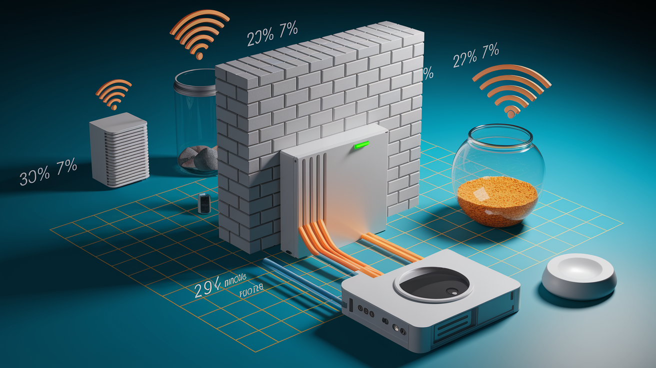
Different building materials affect wireless signals with measurable attenuation percentages. Drywall causes minimal signal loss at 5-10%, enough to notice but rarely enough to cause real problems. Wood studs and plaster add 10-20% loss, which starts mattering when you’re pushing distance limits. Brick and concrete jump to 40-60% attenuation, cutting your effective range nearly in half. Metal causes 70-90% loss or complete signal blockage depending on thickness and whether it’s solid sheets or mesh. That standard 25-30 foot wireless backhaul distance assumes signals pass through one or two wood-framed drywall walls maximum. Add a brick exterior wall or concrete floor into the path and you’ll need to reduce spacing significantly.
Electronic interference sources operating on the 2.4GHz band cause connectivity drops and reduced speeds rather than consistent slower performance. Microwave ovens create intense but brief interference when running. Baby monitors, cordless phones, and some Bluetooth devices generate constant low-level interference. Neighboring WiFi networks on the same channels add congestion rather than interference, but the effect looks similar with devices struggling to maintain connections. Maintain 3-6 feet of physical separation between mesh satellites and known interference sources when possible. If you experience dropouts at specific times, change your mesh system’s channel selection in the management app. Most systems default to automatic channel selection, but manual control helps in crowded apartment buildings where dozens of networks overlap.
Work around unavoidable obstacles strategically. HVAC ductwork, large aquariums, mirrors, and metal-backed insulation all block signals effectively. Test signal strength before permanently installing satellites to identify unexpected barriers. When large metal appliances like refrigerators or gun safes block the direct path between your router and planned satellite location, move the satellite to an adjacent room that routes around the obstruction. Homes with metal workshops, home theaters with extensive ductwork, or sun rooms with metal-framed windows benefit from wired ethernet backhaul through these high-attenuation areas rather than fighting wireless signal loss.
Common household obstacles ranked by signal impact:
Drywall interior walls create minimal impact, so proceed with standard 40-50 foot spacing between nodes without adjustment. Exterior brick or stone walls create significant impact, reduce spacing to 20-25 feet maximum when signals must penetrate these materials. Concrete floors and ceilings deliver severe impact, add a dedicated node on each level rather than expecting good floor-to-floor penetration. Large metal appliances like refrigerators, water heaters, and safes create near-complete blockage, route signals around these obstacles with offset satellite placement rather than through them. Fish tanks and decorative water features absorb signals substantially, avoid line-of-sight paths directly through large water volumes by repositioning nodes to go around. Mirrors and large metal-backed artwork act as signal reflectors and barriers, treat these as solid obstacles requiring alternate signal paths. HVAC returns and metal ductwork create interference zones, maintain 2+ feet of clearance between ductwork and satellite antenna locations when mounting.
Network Configuration Steps: SSID Setup and Mesh Mode Activation
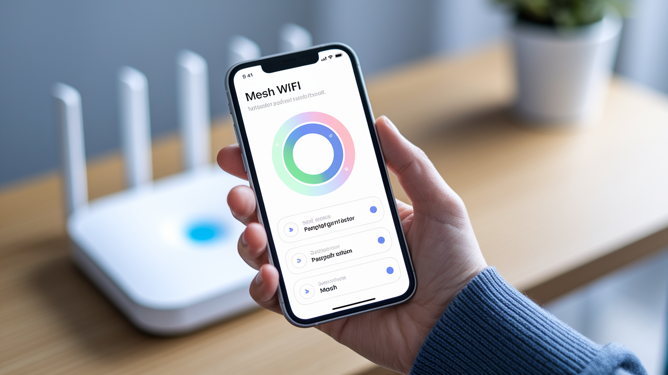
Download your mesh system’s mobile app and power on your primary router connected to the modem. The app discovers your gateway within 30-60 seconds, prompting you to create an account and begin network setup. This initial discovery process works automatically for pre-synced systems like ASUS ZenWiFi, TP-Link Deco, and NETGEAR Orbi families since the hardware ships configured to find each other.
Configure your unified SSID and password so all mesh nodes broadcast the same network name. This single network name is what enables seamless roaming since your devices never manually switch between different networks as you move through your home. Choose a password meeting WPA3 requirements with at least 12 characters mixing letters, numbers, and symbols. The app applies this configuration to all nodes automatically.
Select between mesh mode and access point mode depending on your existing equipment. Mesh mode means your new system acts as the primary router, completely replacing any ISP-provided gateway’s routing functions. Access point mode keeps your existing gateway handling routing while the mesh system only provides WiFi coverage. Most installations use mesh mode for full feature access.
If you’re keeping an ISP-provided gateway in place, enable bridge mode on that gateway to prevent double NAT routing issues. Double NAT occurs when two devices on your network both try to route traffic, causing problems with gaming consoles, port forwarding, and some work VPN connections. Bridge mode turns your gateway into a simple modem that passes internet traffic directly to your mesh router without interference.
Access Point Connections: Adding Wired Devices to Mesh Nodes

Most mesh satellite nodes include 1-4 ethernet LAN ports on the back for connecting wired devices. These ports let you plug in desktop computers, smart TVs, gaming consoles, and other equipment that benefits from stable wired connections. The satellite acts as an extension of your router, providing full network access and firewall protection to anything connected via these LAN ports.
Devices wired to mesh nodes maintain full gigabit or multi-gig speeds regardless of how that satellite connects back to the main router. If your satellite uses wireless backhaul but has a desktop computer plugged into its ethernet port, that computer gets gigabit speeds over the cable even though the satellite itself connects wirelessly. Only WiFi clients connected to wireless-backhauled satellites experience the performance reduction from wireless backhaul. Wired clients always get full wired speeds.
Add an unmanaged gigabit or multi-gig switch to any mesh node when you need more wired ports than the satellite provides. A satellite with two LAN ports can feed a 5-port or 8-port switch, multiplying your available connections for that room. The switch maintains firewall protection and network segmentation since it sits behind your mesh system’s security features, operating as a transparent extension of available ports rather than creating a separate network segment.
Outdoor Mesh Extension: Weatherproof Node Placement for Property Coverage

Outdoor-rated mesh satellites extend coverage to yards, garages, outbuildings, and separate structures on your property. These weatherproofed units mount on exterior walls, under eaves, or on posts with UV-resistant enclosures protecting internal components from rain, snow, and temperature extremes. Position outdoor nodes where you need coverage for security cameras, smart irrigation controllers, outdoor entertainment areas, or detached workshops.
Outdoor ethernet cables require different specifications than indoor patch cables. Use shielded, outdoor-rated networking cables with waterproof jackets and UV protection. These cables withstand years of sun exposure and weather without degrading. Install ethernet surge protectors where outdoor cables enter buildings to protect your mesh equipment from lightning strikes and electrical surges traveling along the cable. Run a drain wire from the surge protector to a proper grounding rod driven into earth near the building, or ground directly to a metal building structure when available. Cable routing under eaves through wire chases keeps cables protected and maintains clean appearance.
Mount outdoor satellites high with clear line-of-sight to other nodes when possible. Elevated positions on roof eaves, tall posts, or building peaks maximize wireless backhaul range by clearing ground-level obstacles like vehicles, landscaping, and terrain variations. Point directional outdoor antennas toward the upstream node they’re connecting to rather than toward the coverage area since the backhaul connection matters more than client device positioning. Most outdoor mesh satellites provide omnidirectional client coverage regardless of which direction the unit faces.
Real-world outdoor distances vary significantly based on obstacles and terrain. One installation achieved 100 feet between buildings with 90-percent throughput despite antennas pointed away from each other with partial metal roof obstruction. Another reached 215 feet with better performance due to direct line-of-sight between roof-mounted units. The same installation achieved 500+ feet of coverage to a front gate by positioning satellites at optimal central locations on the property. These distances exceed typical online specifications claiming only a couple hundred feet maximum range, likely because most published tests occur in densely populated areas with interference from neighboring networks rather than wide open spaces with zero competing signals.
Security Configuration: Encryption and Network Protection Setup

WPA3 encryption is the current security standard for mesh networks, replacing older WPA2 protocols with stronger protection against password attacks. Enable WPA3 during initial setup if your system supports it, falling back to WPA2/WPA3 mixed mode only when you have older devices that can’t connect with pure WPA3. Your password should contain at least 12 characters mixing uppercase, lowercase, numbers, and symbols. Avoid dictionary words, personal information, or common patterns like “Password123!” that attackers try first. Something like “Green$Sky7Mountain!Rain” provides solid protection while remaining memorable.
Guest network configuration creates a separate network name and password for visitors, keeping them isolated from your main network devices and shared resources. Guests get internet access but can’t see your computers, network storage, printers, or smart home devices. Configure guest network access through your mesh management app, typically under a dedicated guest network section. Set a simpler password for guests since they’ll need to type it manually, but change this password periodically if you have frequent visitors. Some systems let you set time limits on guest access, automatically disabling the network after a specified period.
VLAN functionality separates your network into isolated segments at a deeper level than guest networks. This advanced feature works well for isolating smart home devices on their own VLAN where they can’t interact with computers and phones on your main network. IoT devices like smart bulbs, plugs, and cameras benefit from VLAN isolation since their security often lags behind mainstream computing devices, presenting potential entry points for network intrusions if they’re compromised. Creating VLANs requires more technical knowledge but adds significant security for complex smart home installations.
| Security Feature | Purpose | Recommended Setting |
|---|---|---|
| WPA3 encryption | Protects WiFi traffic from interception and unauthorized access | WPA3 only, or WPA2/WPA3 mixed if needed for older devices |
| Guest network | Provides visitor internet access while blocking access to main network | Enabled with separate password, bandwidth limiting optional |
| VLAN segmentation | Isolates device groups on separate network segments | Configure separate VLANs for IoT devices, security cameras, and main computers |
| Firewall rules | Controls traffic flow between network segments and internet | Enable automatic threat blocking, consider geo-blocking for enhanced security |
Device Handoff and Roaming: Seamless Network Transition

Your mesh system’s single SSID architecture means all nodes broadcast the same network name, so your phone, laptop, and other devices never switch between different networks as you move through your home. This eliminates the old multi-router problem where you’d manually disconnect from “HouseWiFi” and reconnect to “HouseWiFi_Upstairs” when moving between floors. Your device sees one continuous network regardless of which physical mesh node it’s currently using.
Automatic node handoff works through background signal monitoring. Your mesh system constantly measures signal strength between each connected device and all available nodes. When your phone moves away from the living room node toward the bedroom node, the system detects improving signal strength to the bedroom node and weakening signal to the living room node. At the optimal transition point, your connection transfers to the stronger node without user action. This handoff typically completes in 1-3 seconds, fast enough that most applications continue without interruption.
You’ll experience minimal disruption during roaming events for most applications. Web browsing, social media, and email continue without a hitch since these applications tolerate brief connection pauses. Video streaming might buffer momentarily during the handoff, then resume at the same point. Video calls on Zoom or FaceTime pause for 1-2 seconds during particularly long-distance roaming events but rarely drop completely. Gaming sees the most impact from roaming since real-time games penalize connection interruptions, which is why wired connections remain preferable for serious gaming setups.
Troubleshooting Common Mesh Setup Issues
Node adoption failures often stem from firmware mismatches rather than hardware problems. If satellites won’t adopt into your network during initial setup, check for available system updates before assuming equipment failure. Brand-new mesh systems sometimes ship with outdated firmware that lacks support for the newest hardware in the product line. Enable automatic updates in your gateway’s settings and let the system run overnight to download and install the latest software. The adoption process usually succeeds after updating.
Ethernet cable damage and quality issues limit speeds even when connections appear to work. A cable showing 100Mbps Fast Ethernet speeds instead of expected gigabit performance might have internal wire damage from being pinched, bent too sharply during installation, or manufactured with substandard materials. Replace suspected problem cables before troubleshooting complex software configurations. Cable quality matters especially on longer runs where poor shielding or incorrect termination causes signal degradation. If you’re running cables yourself, verify each one reaches full rated speed with a cable tester before tucking it into walls or running it long distances outdoors.
Step-by-step troubleshooting sequence:
Verify all mesh nodes show solid indicator lights matching manufacturer specifications for “connected” status rather than “searching” or “error” states. Confirm your modem has internet connectivity by directly connecting a laptop via ethernet and testing speeds before blaming mesh equipment. Check mesh system firmware versions in the management app and update all nodes to matching latest versions if available. Power cycle the entire system starting with the modem (30 seconds off), then primary router (wait for full boot), then satellites one at a time. Test wireless backhaul distances by temporarily moving problem satellites closer to the primary router to confirm range isn’t the issue. Review satellite mesh configuration to ensure indoor nodes haven’t enabled meshing when they should connect via ethernet, creating interference loops that slow the entire network.
Network Performance Monitoring: Speed Testing and Coverage Mapping
Establish your baseline speed by connecting a laptop directly to your primary router via ethernet and running a speed test to a nearby server. This baseline shows your actual internet speeds independent of WiFi performance, confirming what your ISP delivers before you start evaluating mesh coverage. If this wired test shows 400Mbps on your gigabit plan, you know the limitation comes from your internet service rather than your mesh network. Document this baseline number for comparison against wireless speeds throughout your home.
Room-by-room speed testing reveals coverage quality systematically. Walk through your home with a smartphone or laptop running a speed test app, recording download speeds, upload speeds, and latency at key locations like bedrooms, home offices, living areas, and known problem spots. Test near each satellite node to confirm it’s receiving adequate backhaul, then test midway between nodes where coverage should overlap. Consistent speeds within 70-90% of your baseline indicate good mesh performance. Locations dropping below 50% of baseline need attention through node repositioning or switching to wired backhaul.
Your mesh system’s topology visualization map shows which devices connect to which nodes in real-time. This feature in the management app helps identify unusual connection patterns like devices persistently connecting to distant nodes instead of closer ones, indicating potential configuration problems or physical obstacles blocking preferred paths. Watch the topology while walking through your home to verify smooth handoffs occur at expected locations rather than devices stubbornly holding onto distant nodes until connection breaks completely.
Key performance metrics to monitor:
Download speed at each location compared to baseline wired speed from the router, looking for consistent 70-90% throughput. Upload speed matters for video calls and cloud backups, particularly important for home offices and video conference spaces. Latency or ping time to nearby servers, where numbers under 20ms indicate excellent performance and over 50ms suggest problems. Signal strength measured in decibels (dBm) where -30 to -50 dBm represents excellent signal and -70 dBm or weaker indicates marginal connection. Connected device count per node showing whether your mesh system distributes devices evenly or whether one overloaded node handles too many clients.
Bandwidth Management: QoS and Traffic Prioritization
Quality of Service settings ensure critical applications receive adequate bandwidth even when your network gets congested with multiple simultaneous uses. Without QoS, your smart TV downloading a software update might consume available bandwidth right when you join an important video call, degrading your call quality. QoS prioritization reserves bandwidth for designated high-priority devices or traffic types, preventing background activities from interfering with real-time communication.
Priority tiers typically include high, medium, and low categories. Assign high priority to devices and applications where delays cause immediate problems: gaming consoles running competitive online games, computers used for video conferencing, and streaming devices serving your main TV. Medium priority fits everyday devices like phones, tablets, and laptop web browsing that tolerate brief slowdowns. Low priority suits background activities like software updates, cloud photo uploads, smart home device communication, and security camera recording that can wait when bandwidth gets tight.
Configure QoS through your mesh management app’s traffic management or bandwidth control section. Most systems let you assign priority by device, selecting from your connected device list and setting each one’s priority level. Advanced systems also support application-based QoS where you prioritize traffic types like video conferencing regardless of which device generates it. Enable QoS globally, then test performance by running high-priority activities simultaneously with heavy downloads to verify priority enforcement works as expected.
| Device/Application Type | Recommended Priority | Reason |
|---|---|---|
| Gaming console | High | Real-time games penalize latency severely, milliseconds matter for competitive play |
| Video conferencing computer | High | Work calls require consistent upload bandwidth and low latency to avoid frozen video and choppy audio |
| Primary streaming TV | High to Medium | Main entertainment device benefits from priority, but streaming tolerates brief buffering better than gaming |
| Smart home devices | Low | Smart bulbs, thermostats, and sensors use minimal bandwidth with no time sensitivity |
| Background downloads and updates | Low | These can complete slowly without affecting user experience, should never interfere with active use |
Expanding Your Mesh Network: Adding Nodes Over Time
New mesh nodes must match your existing system’s manufacturer since mesh protocols remain proprietary and incompatible between brands. A TP-Link Deco satellite won’t join a NETGEAR Orbi network, and Google WiFi nodes won’t extend an ASUS system. Rare exceptions exist for multi-protocol systems specifically designed for cross-brand compatibility, but these remain uncommon. When expansion time comes, you’ll purchase additional nodes from the same product family already installed in your home. Many manufacturers offer single satellite units for expansion rather than requiring multi-unit packs.
Adopting new nodes into existing networks follows a straightforward process in most systems. Power on the new satellite near your existing network, typically within 10 feet of the primary router during initial adoption. Your mesh management app detects the new hardware automatically and prompts you to add it to your network. Once adoption completes and the new node shows connected status, you can move it to its permanent location. Some systems require the new node to sit near the router during a firmware update before placement, taking 5-10 minutes for the update to download and install.
Node count limitations vary between wireless and wired backhaul configurations. Wireless backhaul systems typically cap at 8-10 units due to cumulative interference and diminishing returns from too many nodes sharing radio spectrum. The TP-Link Deco series recommends 10 units maximum with WiFi backhaul. Systems using wired ethernet backhaul support unlimited expansion since wired connections don’t create radio interference or compete for wireless channels. You can add dozens of satellites when they’re wired, though most residential installations never need more than 6-8 nodes even in large homes over 5000 square feet.
Final Words
A mesh WiFi setup diagram turns abstract networking concepts into concrete installation steps you can follow room by room.
The difference between star topology and daisy-chain, between wireless and wired backhaul, between proper placement and guesswork shows up immediately in your real-world speeds and coverage.
Start with your floor plan, mark distances, identify obstacles, then position nodes where signal testing confirms they’ll work.
Your mesh system will only perform as well as the thought you put into the layout before plugging anything in.
FAQ
How should I set up my mesh WiFi?
To set up your mesh WiFi, connect your ISP modem to the primary mesh router’s WAN port, place satellite nodes 25-30 feet apart through walls or 40-50 feet in open areas, then use the mobile app to adopt all nodes into one network with a single SSID name.
What is the best layout for mesh WiFi?
The best layout for mesh WiFi uses star topology where each satellite connects directly to the main router or a wired node, avoiding daisy-chain setups. Position your router centrally and distribute satellites evenly throughout coverage areas, testing signal strength between placements.
Which is better, a WiFi extender or mesh?
A mesh WiFi system is better for homes over 3000 square feet or multiple problem areas because it creates seamless roaming with one network name. For single dead spots within 20-30 feet of your router, a simple WiFi extender or powerline adapter costs less and solves the problem.
Does Ubiquiti support mesh WiFi?
Ubiquiti supports mesh WiFi through its UniFi product line including the U6 Mesh and U6 Mesh Pro models. These devices work together in the UniFi ecosystem and can be configured for wireless or wired backhaul through the UniFi mobile app and web controller.